


A four-way shuttle failure in a dense pallet storage system triggers immediate pressure: every minute of downtime has a direct throughput cost. While the instinct is to manually extract the stuck robot, the most effective first response is to let the warehouse control system (WCS) re-route traffic and isolate the fault. In projects I’ve commissioned, I’ve seen operators lose more time trying to force a manual reset than allowing the software to re-plan. This guide walks through a systemic recovery sequence—from alarm acknowledgment to preventive system design—drawn from more than ten years of shuttle system projects in industries ranging from cold chain to automotive manufacturing.
Immediate Actions When a Shuttle Fails
When the alarm sounds, resist the impulse to rush into the aisle. Most four-way shuttle systems, including the R-bot platform we deploy, are designed to enter a safe state that prevents collisions even before a human responds. The first actions should happen at the control terminal, not on the warehouse floor.
Open the WMS or WCS dashboard and identify the faulted unit by its asset number and rack location. The system will typically display an error code and a brief description—these raw codes are rarely user-friendly, so refer to the equipment-specific fault lookup table. Confirm whether the system has automatically halted traffic in the affected lane. If the shuttle is positioned clear of the main travel path and no adjacent shuttles are at risk, avoid triggering a full emergency stop. A hard stop across an entire level frequently causes a cascade of task cancellations that take hours to untangle.
From the control room, check the communication status of the shuttle. A dropped Wi-Fi node can produce the same dashboard alert as a mechanical jam. If the shuttle is still communicating, query its onboard diagnostics for battery voltage, motor current, and last executed motion command. This one-minute check often reveals whether the failure is real or a transient communication glitch.
Diagnosing the Cause of Four-Way Shuttle Failures
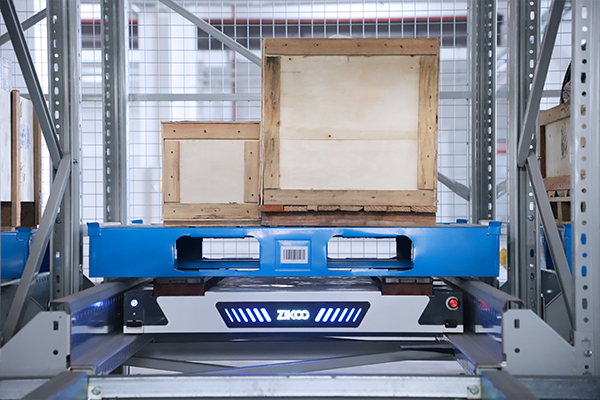
Effective recovery depends on correctly categorizing the fault. I group four-way shuttle failures into four primary domains, each with a distinct set of symptoms and immediate checks. The following table synthesizes field patterns I have observed across multiple installations.
| Failure Domain | Common Symptom | Immediate Diagnostic Check |
|---|---|---|
| Mechanical | Grinding noise, no motion, tilted shuttle position | Inspect drive wheel wear, lift chain tension, rail debris |
| Electrical / Battery | Shuttle fails to initialize, sudden shutdown, low speed | Measure battery voltage under load, check cell balancing, verify charging contact condition |
| Communication | Shuttle unreachable, intermittent position updates | Verify Wi-Fi access point RSSI, check for protocol timeout entries in WCS log |
| Software / Firmware | Repeated route rejection, incorrect pallet detection | Compare firmware version against fleet baseline, review recent path-planning parameter changes |
Mechanical issues are the most disruptive but also the most visible. A worn drive wheel or a bent rail guide will produce a pattern of repeated faults at the same rack location. Battery failures, on the other hand, are insidious: a cell imbalance can reduce effective capacity without triggering a low-voltage alarm until the shuttle is deep inside a lane, far from the charging station. In several cold storage deployments, we traced intermittent shutdowns to battery packs that tested fine at room temperature but sagged below cutoff when soaked at -18 °C for more than three hours.
Communication faults deserve particular attention because they can mimic mechanical jams. If a shuttle loses connectivity for even 200 milliseconds during a lane-change maneuver, the WCS may register it as a collision risk and lock the entire level. Before sending a technician, verify the Wi-Fi coverage map and check for recent structural changes—a new high-bay rack or a metal partition can create a shadow zone that was absent during commissioning.
How the WCS Manages Shuttle Faults and Re‑routing
The true value of an automated shuttle system reveals itself during a failure: a well-configured warehouse control system isolates the fault and maintains operations with near-zero human intervention. This is not theory—I have stood in control rooms and watched a 60-shuttle fleet absorb the loss of two units within the same hour without missing a single outbound pallet commitment.
When the WCS receives a fault signal, it executes a sequence that removes the shuttle from the active resource pool. The algorithm first validates that the fault is confirmed, not transient, by checking for repeated error conditions within a configurable time window. Once confirmed, the shuttle is flagged as unavailable, and all pending tasks assigned to it are re-queued. The path-planning engine then re-calculates routes for the remaining shuttles, treating the position of the failed unit as a temporary obstacle. If the shuttle is occupying a lane that blocks access to storage locations, the WCS dynamically re-assigns lifts and alternate aisles to route around the blockage.
Our PTP Smart Warehouse Software platform, which combines WMS, WES, WCS, and RCS functions, performs this re-routing in under 300 milliseconds per affected task. The key factor is spare shuttle capacity. In a system with 10% extra shuttles—say, 55 units where 50 are needed for peak throughput—a single fault typically produces less than a 5% throughput drop. Without spare capacity, the same fault forces the remaining shuttles to operate at maximum duty, and queue lengths build rapidly.
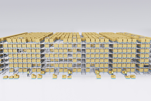
A practical note: the WCS re‑route logic is only effective if the system designer has configured the lane topology and task priorities correctly. I have seen sites where a shuttle failure at a critical merge point could still cripple the warehouse because the WCS was programmed with a simplistic “nearest available” algorithm that did not consider downstream congestion. During commissioning, test not only normal operation but also induced failures at each potential bottleneck.
Manual Recovery for a Stuck Four-Way Shuttle
When the shuttle cannot be re-routed and physically blocks a must-use lane, manual extraction becomes necessary. Do not begin this process until you have confirmed in the WCS that all power to the affected lane has been isolated. Four-way shuttles carry lithium batteries with significant stored energy, and a partial isolation can leave drive motors energized enough to cause injury.
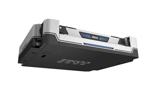
The recovery sequence starts with confirming the shuttle’s mode. Most units have an onboard manual release that disengages the drive and lift motors. On the R-bot, this is a mechanical lever accessible from the aisle side. Engage it and verify that the shuttle can be moved by hand or with a service trolley. If the shuttle is tilted or stuck due to a deformed pallet, use a pallet jack to gently separate the load before attempting to slide the shuttle out.
Once the unit is on a service cart, connect a diagnostic tablet and pull the full event log. Do not clear the error memory and send it back into operation without root cause analysis—a shuttle that has been manually recovered three times in a month is a process problem, not a robot problem. Common repeat-offender issues include a mis-calibrated lift height sensor that causes the shuttle to strike pallet overhangs, or a floor unevenness that triggers an out-of-level safety trip in the same lane every cycle.
If your facility does not have an in-house technician trained on shuttle maintenance, coordinate recovery with the supplier’s remote support team before sending anyone into the rack. Many faults can be cleared remotely through the WCS diagnostic interface. A video call with a supplier engineer who has access to the same dashboard often resolves the situation faster than dispatching a local technician who is seeing the machine for the first time.
Handling Four-Way Shuttle Failures in Cold Storage
Cold storage warehouses magnify every vulnerability. Lubrication thickens, batteries lose effective capacity, and condensation can short signals on exposed connectors. When a four-way shuttle fails in a -20 °C freezer, the recovery window is not the hour you can afford in an ambient warehouse—it is the twenty minutes before product temperature deviation becomes a quality issue.
The fundamental requirement is a shuttle spec that matches the operating environment. Standard lithium batteries that deliver a full eight-hour shift at 20 °C frequently drop to four hours at -18 °C because the electrolyte conductivity falls and internal resistance rises. For cold chain projects, we spec the R-bot’s dedicated low-temperature pack, a 51.2 V / 40 Ah lithium unit that sustains eight hours of continuous operation down to -25 °C. The low-temperature charging port design also eliminates the need to remove batteries to a warm room—a practice that invites connector wear and thermal shock damage.
Preventing moisture-induced faults is equally important. The cold store’s defrost cycle generates humidity that condenses on cold metal surfaces. We apply a special conformal coating to the PCBA (printed circuit board assembly) to prevent short circuits, and all‑rubber buffer wheels eliminate the metal‑on‑metal corrosion points that can seize after repeated freeze‑thaw cycles. If your shuttle was originally specified for ambient use and is now being moved into a cold zone, do not assume the electronics will cope. We have replaced control boards that failed within two weeks because the enclosure’s IP rating was insufficient for the actual humidity swing.
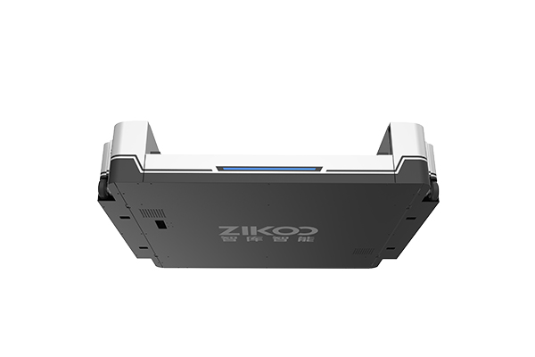
For immediate recovery inside a freezer, the protocol differs in one critical way: do not bring a frozen shuttle out to a warm maintenance bay without first bagging it. A sudden 40‑degree temperature jump will drench the internal electronics with condensation faster than any drain. Instead, perform a preliminary diagnostic inside the cold zone, clear the error if it is a simple sensor trip, and only extract the unit to a temperature‑controlled transitional buffer area if hardware repair is required.
Preventing Future Failures Through System Design and Maintenance
The best recovery is the one you never have to perform. Designing the shuttle system for fault tolerance from day one costs a fraction of the productivity lost to repeated extraction events over a ten‑year deployment.
Spare shuttle capacity is the single highest‑return investment. For any fleet of 50 or more shuttles, I recommend budgeting at least 5% additional units above peak throughput requirements. These spares can be rotated through active duty to normalize wear and should be configured identically to the primary fleet so that a failed unit’s tasks transfer instantly without the WCS needing to recalculate payload limits or speed profiles. At one automotive parts warehouse, adding three spare shuttles eliminated a recurring bottleneck that had caused 12 production‑line stops in the previous quarter.
On the maintenance side, baseline the following schedule: weekly battery impedance trending, monthly drive wheel thickness measurement, quarterly full‑speed diagnostic runs across every lane, and annual firmware audits. Our PTP platform’s maintenance module can log each checkpoint and flag deviations before they become hard faults. A shuttle whose wheel diameter has worn by more than 2 mm will begin to drift in positioning; catching that during a monthly check prevents a lane‑blocking jam during a busy shift.
Remote monitoring further reduces reaction time. When the WCS streams real‑time shuttle health metrics to a cloud‑based dashboard, we can often identify a degrading battery cell or an increasing motor current trend days before the shuttle triggers an alarm. For global operations, this means the supplier’s engineering team sees the warning light at the same moment the on‑site operator does. In several instances, we have dispatched a replacement shuttle before the warehouse manager realized there was a problem.
If you are currently evaluating a system upgrade or a new build, your supplier’s willingness to demonstrate a live simulated failure and recovery during a FAT (factory acceptance test) is a reliable indicator of how the system will perform under real stress. Ask to see the WCS re‑route a task while a shuttle is deliberately taken offline. If the response time exceeds one second, the failure‑handling logic is likely too simplistic for a high‑throughput facility.
A four-way shuttle system that has been designed for resilience and supported by a disciplined maintenance cadence will not eliminate failures entirely—no electro‑mechanical system does. What it will do is convert a failure from a warehouse‑halting crisis into a routine event that the system absorbs without the inbound and outbound teams ever noticing. For operations engineers evaluating their risk exposure, send your current shuttle count, lane layout, and throughput profile to info@zikoo-int.com or call (+86)-19941778955. We can model the impact of a single failure on your specific configuration and recommend the spare capacity and software settings that will keep your operation moving when the next shuttle goes down.
Common Questions About Four-Way Shuttle Failures
The most common root causes of shuttle failures
In the data I have collected across dozens of installations, three root causes account for roughly 70% of unplanned stops: battery degradation (including cell imbalance and low-temperature capacity loss), drive wheel wear beyond the maintenance limit, and Wi-Fi communication dropout at lane far ends. Battery faults tend to increase sharply after the 2,000‑cycle mark and are predictable with regular impedance checks. Drive wheel wear can be prevented entirely by replacing wheels at 85% of their design wear limit rather than waiting for a failure. Communication issues are solved by a site survey that confirms RSSI above -65 dBm at every shuttle operating point, including after new racking is installed.
Whether a single shuttle failure stops the whole warehouse
A properly configured WCS isolates the fault to the affected lane or level; it does not shut down the entire facility. The rest of the fleet continues to operate, re‑routing around the blocked zone if spare capacity exists. The whole warehouse only stops if the failed shuttle occupies a single choke point that all traffic must pass through—typically a central lift that was not designed with a bypass. This is a system design issue, not a shuttle reliability issue. In new projects, I insist that every primary lift serve no more than 60% of a level’s shuttle population, so that one offline unit cannot create a single point of failure.
Whether automated shuttle systems need a dedicated maintenance team
A dedicated automation technician is worth the investment once the fleet exceeds 20 shuttles. Below that count, a supplier service contract with remote diagnostics and quarterly on‑site visits can cover the workload. The critical point is that the in‑house facility team must have at least one person trained on the specific shuttle model—someone who can execute the manual release procedure and perform basic voltage checks without waiting for a supplier engineer to travel. We provide this training as part of commissioning, typically two days on‑site with the actual equipment.
If a four‑way shuttle can be repaired on‑site
Most repairs can be performed in a maintenance bay adjacent to the rack. Swapping a drive wheel, replacing a battery pack, and re‑calibrating sensors are all achievable with the correct tools and spares. Board‑level repairs and motor rewinding should be handled by the supplier’s service center. The key to on‑site efficiency is having the spares on the shelf before the failure: a three‑day wait for a replacement battery creates more downtime cost than the battery itself. I recommend a spares kit that includes one complete battery pack, two drive wheels, a spare lift sensor, and a set of communication antennae per 25 shuttles.
If older shuttle models can be retrofitted with modern fault‑tolerant software
In many cases, yes. The core motion control and battery management on shuttle models from the last five years is compatible with current WCS platforms. The limiting factor is usually the communication protocol—early CAN‑bus implementations may not support the real‑time diagnostic streaming that modern re‑route algorithms depend on. We can assess the upgrade feasibility by pulling the shuttle’s firmware version and controller hardware revision. If your current system lacks automated fault isolation and you are spending too many hours on manual recoveries, send your equipment details and a recent fault log to info@zikoo-int.com. We will confirm whether a software upgrade can bring your existing fleet to the same fault‑tolerance level as a new deployment.
If you’re interested, check out these related articles:
PTP Intelligent Warehouse Software Empowers Enterprises for Smart Upgrades
Multi-Scenario Smart Adaptation: Zikoo’s Six-Way Shuttle Powers the Digital Transformation of Warehousing


